Author: mj

The new Mistress

Just cuddling the new mistress…

It’s a slightly broken, carbon fibre wing from a Porsche 996 GT Cup car.  These are a factory Porsche race car, so its a light weight wing that actually works!

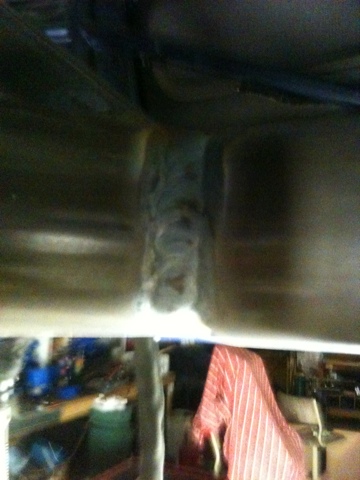
It was on a car that crashed at Wanners the other week.  Luckily for me, the car owner has enough money that he just wants a new wing, so, as this one was going into the bin, I grabbed it from them.  It has cracked on the underside when it attaches to the mounting plate, which has come out.  So, this needs to be glued back in, and there are a number of small splits in the carbon that will need to be ground out and patched up, but its all very do-able.  I’ll then need to make the end plates and a set of mounts to attach it to the car.  I have made templates of the Porsche ones, so I’ll make an alloy mount, and composite end plates.

You can see the small areas of damage in the pics above.  The large slot on the right hand picture is where the wing mount gets glued in (The mount is the black bit in the left picture).

As for actual progress, the frame is all welded now, the seat rail is about 80% built, and 50% welded in.  Just need to make one bit, tweak another bit, then finish weld it and the frame in the middle of the car will be done.  Hopefully I can get back out there tonight as soon as it cools down a bit (it’s still 35 deg!).

Next on the list is the mounts for the seat, and mounts for water, battery and fire exh. Then I need to connect from the new frame, to the existing front chassis rails – Need a little bit more metal tube, so won’t have that till next weekend.

Welding, welding, welding…

Got 2hrs of work in after the kids were asleep, all of it welding… Still have another 2 or 3hrs to go, plus welding in the seat rails that I haven’t built yet.

On a more interesting note I think I have managed to score a Porsche 996 GT3 Cup car (a couple of year old Porsche factory race car) rear wing. It’s got some damage, but nothing the composites wizard JC won’t be able to fix. We’ll then be able to make a mold of it and make up proper working wings for our cars. I’ve been told I can have this wing, here’s hoping that it all pans out.

20110412-000746.jpg 20110412-000805.jpg

Sunday’s Toil – The Final Toll

My lovely wife got me some grinding discs and sanding belts on her way home, so there were a couple more things that I could get done.

Got another 4 bars into the structure, so the frame is complete apart from the seat rails. I’ve designed it all, just need a small piece of tube to finish that off.

Put the seat in to check the size of the tunnel and it’s shape, to make sure the seat will fit as it has a very wide lip on the front edge of it.  The funny shape that I’ve had to make the tunnel means that it fits perfectly 🙂  You can also see the extra headroom now that the seat has been lowered on the new floor.

All of the floor that I’ve taken out, weighs in at approx 25 kgs.  The tubes that I have used so far come in at 9.8kg.  So, add some weld and lets call it 10kg.  This means that we are currently on target to be under the weight of the existing floor, but at the same time it’s already sooooo much stiffer, and the composite floor skin is not even on yet!

PS.  I LOVE the rain!!!

Sunday’s Toil – Progress Update

The Tig is out of gas, the Mig’s now out of gas and I’ve run out of cutting discs for the grinder!  Luckily the F1 is on, its time for a rest for an hour.

Didn’t get anything done yesterday – Family day plus mowing the lawn, etc etc.

Got a few hours today, with these results.

Just another two diagonals to go on each side of the trans tunnel and it will be all tacked in.

Will get some Argon for the Tig on Monday, then the hours and hours of welding begins – luckily its quiet so I can do it at night.

In the dog house

Yesterday I managed to go and get the majority of the Chrome-Moly tube that I need for the floor.

After getting home, I was banished to the shed – so I went to work.

Mounted the bender and had a crack at bending the tube – it wrinkled 😦   The bender works fantastically on thicker wall CDS tubing, but not on this thin stuff in moly.

I wanted to have nice little bends in the tube at the ends, so it nicely lowers the floor a little bit more.  Can’t do that, so, onto plan B….

The main cross is now tacked in place, and I put the motor back in to check how everything sits.

Once it started getting late, I stopped using the angle grinder, and layed down under the car to plan out how to do the next bits.  After that nice little rest, I started on the new pedal box.  This new one is going to be floor mounted, as it give me more room for the engine up under the dash.

The accel, brake and clutch pedal parts all cut out.  Still have the base plate to cut out, but its all marked and ready to go.  Next thing to do with these is to start drilling holes in the accel and clutch pedal parts to make them lighter.

Stop Stressing!!!

Ahhhh, don’t you just love corny titles…

The last two nights has been devoted to getting ready for building the new floor frame.

Picked up the bender last night (Thanks Neil!!!), tonight’s been design work, optimizing the tube sizes for max strength and min weight.  I’m getting the hang of SolidWorks now, and while this is not the full cage, its a sample of how its coming along under a stress test simulation if the car was hit in the passenger side A pillar at a 45deg angle.

I’ve got some more bars to add to finish the cage, and the floor design, will get that done tomorrow night and then the analysis starts.  Substituting smaller tubes into the areas of low stress, and adding bigger ones to the areas of max stress, all while applying different forces, simulating different things – like hitting a curb, different crashes, roll movements, etc.

Move along, nothing to see here

No pictures, but got another couple of hours of work done this afternoon.  Got the rest of the floor sections accurately trimmed, including removing the floor from under the roll cage foot plates.  I want to connect the lower bars directly to these foot plates, rather than just attaching it to the sheet metal on the floor – for max strength.  Also welded up a lot of sections of the cage that could not be reached when the floor is in place.

I’ve also removed the rest of the wiring loom from the car, to get it all out of the way while welding etc.

Have also done all of the measurements and weight calculations for the floor tubes.  From the diff through to the under dash bar, all of the tubing will be about 14kg.  This includes items like the seat mounts.  I’ve already taken about 18kg out, and the front seat rails are still in on both sides, as is the tunnel (left in for reference for now).  As soon as the main tubes are tacked in and all sized, the rest of the seat bars and the tunnel will be cut out.  So I’m on target to be a little lighter, or worst case the same.  The difference now being, is that there will not have to be the extra 10kg of underfloor for the aerodynamics.

I’ve also designed the new tubes for replacing the front end.  This is a reasonably large chunk of work to now, but I might do it anyway, as it will be more work and more difficult later…  Time will tell.

Need to make a 100% choice on colour for the car and go and buy a small amount of it, as there are a number of items that I will be able to paint now, that I won’t be able to reach once the floor and firewall goes back in.

So, need to go borrow a tube bender and buy some moly tube tomorrow, cause I’m ready to start!

Flintstones, meet the Flintstones…

The chassis rails and floor on the car is really beat up, from many rounds of mods, from racetrack kerbs, and off-road excursions :/

One of the things that I keep promising myself this build, it to do it right the first time.  I too often get caught up on deadlines (ie events) and build it to a level to meet the event date.  Looking at the effort that is was going to take to repair the floor, I decided to just cut it out and make my own one, both lighter and stiffer than the previous one.

Doing this also gives me the advantage of building a totally flat floor for the underside of the car – good for aero!  With the current floor, I would have to have two floors to make the lower one flat – and that’s weight that I don’t want.

The white tape, and wire are mockups for where the new bar work will be.

Another plus of re-doing the floor is that I can get everything inside (including me) down lower another 30-40mm.  Better for CofG.

Now, we need to work out what tube sizes I’ll be using, to meet the target strength and weight.


It’s back to school time

Today’s newest acquisition

Once the firewall has been rebuilt in the car, the next job is getting the bonnet, bumper and other related cooling areas modified so that the car can be repainted.  So while the weather is hot, some time will be spent working out the most efficient way to get air into the radiator and intercooler, and how to get it out as fast as possible, hopefully adding downforce at the same time (or at a minimum, not creating any lift).

This book goes much further than that, with wings, splitters, undertrays, diffusers etc all covered, and these area’s will be exploited after the car is back running again, as they are all areas that can easily be added on later.

With the aero experimenting that I have done so far, the biggest challenger in all of this is going to be getting enough front downforce to be able to match the downforce from the rear diffuser and wing.  This is the reason why I’m investing time now to get the cooling intakes and exits as best as they can be (as they are all in the front).


I have seen, the light…

This really should have been “Diversions – Part 5 of 4,675,432”, but I’m too excited, so needed a better title!

I’ve been growing increasingly frustrated when trying to work under the car at night, under the light of a torch, so after mowing the lawn, concreting in the posts for Jo’s new half wall outside, I started.

First off, cheers to Shane for giving these fluros that he pulled out of his place during his renovations.  Each fluro is a twin, 36w job, and I’ve mounted one one each side of the posts of the hoist (4 twins in total!)  I’ve still got some minor cleaning up of wiring to do, but its effectively done.

And its BRIGHT!!!!   I think that I could easily remove one tube from each fluro and still have heaps of light!

It’s so bright under there now that even with my iPhone, taking a photo of under the car looks like

Just a random shot, for good measure…

So, off to Bunnings tomorrow to get a couple of little bits to finish it off, pending my F1 commitments of course 🙂

I can’t wait until I get the shed wall/roof insulation done, so that I can get the lights on the roof done.

New World Record!

Two shed nights in a row!

Gearbox mount is done, although it looks nothing like what it did yesterday.  I figured out that flipping it upside down (in concept) would mean that I could take advantage of the strength of the small tube, and make the whole thing a lot lighter.  So, the bracket go all cut up, and I started welding again…

So now, this tube bolts to the gearbox.

And the tabs are on the main gearbox x-member

So, when they are together…


Sorry for the poor pic quality – iPhones taking photo’s under torch light doesn’t lend itself to quality.

It’s really starting to annoy me that I don’t have my proper lights in the shed put up yet. Out in the open area’s its not too bad, but trying to assemble parts under the car is giving me the ……….

So maybe tomorrow night needs to be dedicated to lights, instead of car.  I feel Diversions, part 5 coming on.

Anyway, the gearbox mount is all done, all painted up and fitted!

Shed time!

Well, it was only 1.5hrs, but got a bit done tonight on the gearbox mount.

Machined the alloy crush tube, the outer moly tube, cut and welded the bracket.

The bracket needs some little braces and a finish off (round off the corners, etc), but its almost there.

As for how these bits go together….   The larger bracket bolts to the gearbox with the studs.  The purple poly pieces go inside the large tube.  The alloy tube goes inside all of this.  The bolt goes through the tabs on the main bracket, and through the alloy tube, locking it all together.  The final piece of the puzzle – the larger tube will be welded onto the gearbox cross member, that is bolted to the shell of the car.

The engine mounts that I have already done are the same configuration.

Until next time.

A history lesson – Brakes

The idea behind me doing this was to chronicle what I’m building.  As I’m still on the couch sick, nothing new is being done, so I thought I’d share some old pics.

These are from the big brake upgrade of 2004 (And they have since been upgraded again, twice :))

Burning the old bushes out of the knuckles – this stuff stinks.  Of course, with my usual knack of wanting to make my life harder, I also swapped out all the rear bushes with nolathane at this point too.

Front end all apart…

New Z32 calipers, all painted up with nowhere to go.

Rear caliper, after painting and re-assembly

All corners assembled and ready for fitting.

Ohh, and the rims in the post above, looked like this after being sanded down and repainted.  During this swap I went from the 4 stud to the 5 stud pattern.

The 5 stud swap used s15 lower control arms, which are longer.  nice for camber, not for tie rod length.  New longer ones were needed.

Rear brakes assembled.  New bushes and everything are in place.  Yes, I’ve got no shoes on.  I’m just glad that its a downward camera angle.

Front brakes done.

There is a bit of irony in this shot above, stock s13 front suspension and AP600 Racing brake fluid…

All back together, new brakes all round, suspension bushes, rack ends and rims

Her old home….

And just for some more useless nostalga

My first ever pair of R-Comp tyres – secondhand of course.

On our next trip down memory lane we’ll get into some of the more serious stuff.

PS – a special one for you JC.