Fires and walls

Got a couple of hours done late this arvo.  Started work on the firewall, this separates the engine from the inside of the car, very good especially if there is a fire in the engine bay 🙂

I started working on the drivers side, as this is going to be the most complex side, due to the tight spaces around the pedal box.  I started by making the whole piece in sections of cardboard, all stuck together with tape.  Once this was all done, I had a template to start the metal work.  I decided to make it in two large pieces, with a third piece to form a complex angle that joins the two panels together.

So, the two large pieces are tacked into place.  I’m making this side out of steel and will be welding it in, as this is the side where my feet will live.  The panels on the other side will be in alloy and will be removable panels to allow easy access to the engine.

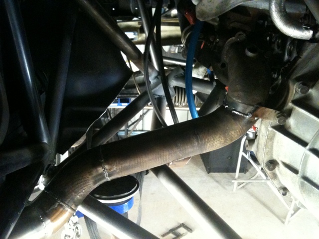
The oval slot, middle top in the pic, is for the steering column  to pass through.  The gap between the sheets, center of pic, will be filled with a separate panel that will run at an angle to the two sheets that are visible in this pic.  This angled piece is to allow clearance for the intake on the engine, but to also keep enough room for the clutch pedal to be fully depressed (clutch pedal not attached in this pic.)

The left side panel has three small bends in it to make it fit nicely against the existing tube work in the car, with another bend at the bottom to make it fit snugly under the pedal box but still leave enough room for a clutch foot rest (it’s going to be a small one!).

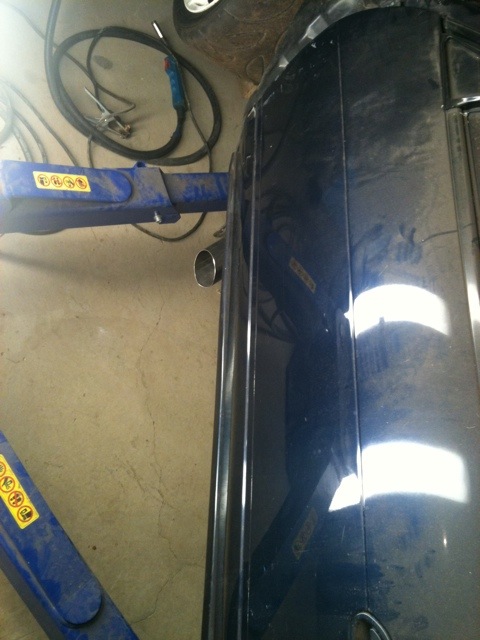
The next pic shows the right side panel nicely tucked into the roll cage, with a single 90 degree bend in it – bent on the folder that I made 🙂

I have tucked the interior panel into the cage like this as the original metal behind this area is full of different holes, not allowing a nice place to seal the sheet metal to.  Also, the longer term plan is to remove the factory material that is behind this section, so doing it this way allows this to be removed but leaving the inside of the car sealed off.

From the bottom of this right side sheet, another panel will run from here down to the back of the pedal box, sealing that section off.  This will leave the brake cylinders inside the engine bay as this is going to be the easiest way to access them if work needs to be done on them and it will keep all the brake lines outside of the cabin.  I could have built the firewall to keep the cylinders inside the engine bay, but it would have been so tight around the cylinders it would have made them really hard to access and the whole pedal box would have to be removed to change a cylinder.

I ran out of gas for the Mig welder, so that’s where progress stopped for the night.  Next on the list is the two remaining panels to seal off this side of the car, hopefully tomorrow night will see a little bit more progress.

I finally feel like the car is getting more complete, rather than further destroyed…

Steering complete

Got some time in today and got the steering rack mounts all complete, and the steering column all complete.

This is the mount for the steering rack.  The round hoop sections at the bottom of the pic is where the steering rack goes.  There are then two other hoops that bolt on underneath, holding the rack in place.

These are now painted all nicely in gloss black (still just in undercoat in these pics).

Then it was onto finishing off the rest of the steering column.  I had been out in the morning at some car wreckers and found a spline of the correct type to fit the universal joint that I was using.  So I cut the splined shaft off the part of steering that I got from the wrecker, machined part of it down in the lathe so it would fit inside the steering column that I had made previously.  So once this was circular and also plug welded (don’t want this bit falling off :)), then painted it was complete.

That pretty much finishes up the the work on the main mechanical systems on the car.  There is a small bit of welding to finish off once I get the motor out, but that will have to wait.  Next on the list to do is to construct the firewall and the small piece of floor in the rear section of the car – where the original rear floor will meet the new ‘aero’ floor.

A little update

Went and picked up a ‘big boys bed’ for little Cody, so spent the morning collecting and setting that up.  The did the lawns, played with kids etc.

Once they were in bed, got another few hours in the shed.

So now the passenger side is 95% done, just need to finish weld one tube.

This is how it looks now underneath.

Now all I have to do is all of that again on the drivers side :/

A big day

Started the day planting some more plants, go some freebies from the parents and another lot from the next door neighbors.

So I didn’t get out to the shed until about 3pm, but that was the start of a long day.

First job was to get the left side suspension fitted.  I had to machine down a bunch of the spaces to fit the new mounting points.

I then compressed the front suspension and strapped it up at the point that the wheels will be when the car is sitting normally on the ground.  I’ve done this so that I can align the steering rack up to get it all spaced correctly for when the car is sitting normally on the ground.

I then started work on the passenger side mounts for the steering rack.  I made up the two hoops to clamp around the rack, then it was onto connecting these to the chassis of the car.

I wasn’t happy with the stiffness of the brackets on the car frame, so I came up with a new idea.  The old idea was designed so that I had some adjustment.  As it turns out there is quite limited space down there in front of the motor, so this time we are going a fixed mount.  So, the new idea…

I’ve decided to put some inserts into the main cross tubes, and then make more of a lattice type structure to hold the rack in place.

So, after a bunch of work with the hole saw, we had 5 new holes.  I then made up 3 different sizes of inserts to weld into these holes.


A bolt will pass through these inserts and into a threaded stud (shown in some of the pics already bolted on).  This threaded stud will have the other tubes that connect to the steering rack.

Some more random pics of progress.

These will probably make more sense over the next few days as I progress.

I also made some progress on the last component for the steering system, adding the short link and a universal joint.  The last bit that I need before the steering is complete is a short section of spline to fit the universal joint.

Time for bed!

It’s Friday night

Spent some time cleaning up, and making some new bits up for the lathe and the shed.

I drilled and tapped some proper mounting points for the extra axis that I purchased for the lathe, so that’s now all ready for use the next time I need it.

I had also gotten some new tips for the cutting tools on the lathe, so I fitted them as well.  I then got to lining all the tools back up in the lathe, getting the tool heights correct again.  I also fitting the new parting off tool that I got.

Apart from that, a bunch of cleaning and packing away getting ready for a big day tomorrow.


More tower building

After a few hours of round the house, mowing lawns etc, I got stuck into the car again.

Today was continuing with the front strut towers.

First was to finish the passenger side by adding an an extra bar, and connecting the main rollcage tube to the new strut top.

I tacked welded in some temporary some bracing between the front caster rod mount and the existing from chassis rail (the funny cross in the bottom right of the pic above).  This was to give it enough strength to hold it in place when I cut out the sheet metal around the old towers.  This metal is going to be replaced, but with a series of flat panels that are much easier for the to make 🙂  The front sections will be replaced as well, but for now I need them to stay lined up so that they can be used as reference points as I build the replacement sections.

I added in the final bars to complete the main cross section that joins the left and right strut towers together.

Then started working on the drivers side, copying all of the same tubes and other pieces as the passenger side, then cut away all of the inner tower sheet metal on this side as well.

I then needed to make to top cap for the towers, for the front suspension to bolt onto.  I have designed a top to give me the same camber adjustment that I used to have, but with one less layer of metal than I had previously.

I’ve cut out the outer circular shape for the other side, but have not yet cut out the inner slots – so that’s the next job when I get another chance to get back into the shed.

New towers

Got another 2hrs of work done, this time the front end tubing up to the top of the strut towers.

I machined up the larges rings for the top of the towers, cut out the standard strut top and tack welded the new one in.  Then I made the tubes that run from the strut top to the other parts of the car.

This large ring will have a top welded onto it, where the top of the suspension will mount.

Half of the original strut top mounting plate won’t be used with this new mount, as I’ll be integrating two of the parts into a single piece, without losing any adjust-ability.  The joys of a specific build – rather than having to contend with ‘standard / mass production’ parts and way’s of doing things.


Another view


So next job tomorrow is to do this same thing to the other side of the car, connect up the last few bits of chassis tubing on the other side, then make the new top plates.

Good days and bad days

Had a good day on Wed, got home early from Targa West recci and so got a few hours in the shed!

I was going to make this front section a bolt-on affair, to make getting the engine out easier.  It was going to be hard, and not very light, and then I had a brain wave (yes, they happen once in a while) and have come up with an easier way to get the engine and gearbox out easily, in one peice.  More on that later…

So, with that instead of having to make complicated mounts, I could just weld everything in.

There are still a few bits that I have left to do, once I buy another small bit of moly tube.

All the front end is now all nicely tied together, all the way up to the new strut top mounts that I’m going to make.

Some more angles…

Then it was onto building the mounts to hold the steering rack in.  It’s all adjustable in both dimensions, so that I can adjust bump steer as well as akerman angle.  This made it a little harder to make than it should have been, but…..  I can’t wait until I can get a mill, cause I could have made the brackets out of alloy a lot faster and nicer than the steel ones that I’ve done.

I made such good progress in these hours – was a good day.

Thursday got home from recci day two early as well – things only got worse from there, so no more progress to report.

Until next time…

Mounts, mounts and more mounts

Yesterday was some cleaning up around the yard, making a new vegi patch, doing retic, planting seeds, then fertilizing all the fruit trees, all the gardens and the lawns.  By that time the day was nearly over, but managed to squeeze in a couple of hours on the car.

Got the lower a-arm mounts made, and gone one of the tacked onto the frame in the required location on the chassis.

There are three mounting locations available for me to test out when its all running again.  The lower most hole is at the same location as the modified mount that I had on the original sub-frame.  This now gives me the option to go higher than that point to test out how the car feels with these different roll centers.

Got a good chunk of car time today were I continued with the suspension mounts.  This time it was on the caster arm mounts.

Once I’ve added the last chassis bars to this mount, I’ll profile it to remove the excess material (like the lower a-arm mounts have been)

I then started preparing the mounts for the steering rack.  I’ve cut out the profiles that are needed to mount the rack, so they will fit tightly over it locking it into position.  Didn’t get a pic of these, so you’ll have to use your imagination 🙂  These will bolt onto the main sub-frame that will run across the engine bay.  These bolt locations will be adjustable up and down, as well as for and aft via some shims.  This will allow me to make changes to help take out any bump steer and also to change the amount of Akerman angle that the steering has during a turn.

Next on the list was to build the sub-frame to hold the steering rack mounts into place.  I didn’t have the metal I needed, so I spent some time trying to work out what the framework in the front end will look like.  I used some high tech masking tape to mock it up :).  I’ve tried to set the bar work up so that it will be easy to change to work at its best once I have changed the front suspension over to double A-arms – rather than the MacPherson strut setup that it has now (A-arms are a much better race suspension, but the mount at a different location).

Pic on the left is taken from above, the second one taken from underneath.

The framework is going to be quite extensive, so to determine how I was going to get things like radiators and intercoolers to fit I put them in.

The whole assembly will be moved back a little bit from the photos here, as I have now removed the coolant swirl pot and I’m going to mount it on the side of the motor.  This gives me another 100mm to move the radiator and intercooler back.  Also on the list is to cut off the outlets of the intercooler and radiator and rotate them around to point them in the right direction to suite their new homes.

I made a few adjustments to the proposed frame after this fitting, to make better use of the tubes and to reduce the size of the mounts that will be needed to hold the rad and cooler in place.

I’ve taken the measurements of all these tubes, now I just need to work out the tube sizes required so that I can buy a couple of them tomorrow.  I need to analyse the forces on the tubes in order to select the right tube size to make it strong, but also very light.  A tube that is put into compression needs to have a larger diameter to take the forces.  A tube that is purely in tension can be a much smaller diameter (ie lighter), but may need a higher wall thickness.

Until next time…

See my 9 inches of glory

Started work on the front suspension last night, and have the right front mocked up in place to start designing the mounts for the suspension arms and the steering rack.

As an experiment, I put the old rear rims and tyres (255 wide tyre on a 9inch rim) on the fronts, and they actually clear the struts with the current setup.  So I put on the 25mm wider guards that Neil got a hold of, and it actually all sits very nicely in there 🙂  I previous had 8″ rims with a 240 width tyre – this extra rubber should mean a good deal more grip.

The wider guards actually looks quite nice, the extension of width is quite subtle.

Ohh yeah, nice and FAT!  JC – I’m coming for ya!

Now, to find some 10 inch rear rims, so that I can get some 280 or 300mm wide tyres on the rear 🙂

More soon I hope…


Still more work, still no play…

Only two more days until the birthday party, so the pain is nearly over…

The fence out the back has now had all its poles cut to proper length and re-oiled, the rear gate now has a proper latch, the front fence is now a lot more complete than it used to be.  30 odd new little native plants have been put out the front now as well.  Add in some more paving, digging some trenches for water drainage (and a ‘quick’ trip to wanneroo raceway to watch car do laps) and the weekend was over…

So while there is hasn’t been any car progress in terms of work, I’ve purchased some composite alloy sheet for the floor.  No progress with it, but at least the sheets are in the shed.  Same goes for some lexan sheet – super tough, lightweight plastic for new side and rear quarter windows.

More soon…

Small Steps…

Spent most of the weekend doing house stuff, getting ready for Sophie’s birthday at the end of the month.

Only managed to get about an hour on the car over the course of the weekend.  I used my new bender to bend up some sheet to start building the firewall and floor.

This pic is from inside the front wheel well, looking back at where the pedals are.  So this section is now sealed up.

Another view, from a lower angle.

I also made the panel to cover the upper part of the transmission tunnel – the section where your radio and air-con controls would normally be.

I also cut up my old exhaust, so that I can use the bits to make the new exhaust.  The ‘new’ parts are now cut up and I’ve mocked the new exhaust up, with the bits all taped together.  I’ve just got to make the final outlet in an oval shape, and then the main fabrication of it will be done.  The rest of it is ready to be final finished, then welded.  Once that is done, I’ve just got to add two mounts to it.  One will go from the first section of the exhaust to the gearbox – to take any flexing load off the back of the turbo charger.  There will be another small mount near the outlet, that is going to be near the front edge of the passenger door.


Shed loads of progress

Got a lot done today, in not too many hours.

I machined up 6 threaded inserts to mount the pedal box into the tubes of the chassis.  They are all lined up and welded in now, so the pedal box mounting is complete!

Next, was some work to finish the steering column.  I ended up cutting off the very end of the mount up near where the steering wheel is, cause I was not happy with it.  Made a new design that I’m happier with.  Also pulled all of the column apart to finish drilling the holes where the steering wheel mounts, and to paint it all.

The I moved onto the lower mount and built and fitted that.

The shaft is now also cut to its proper length.  I kept going with the steering theme, and fitted the steering rack temporally to work out the final bits of the steering.

I then cut up the old steering to get the splined ends, to turn them into the new section of the steering.  So thats now all cut to length and painted, ready to be fitted.

Then I bolted the pedal box back in, and the seat and steering wheel so that I could check the fitment of everything.  Sitting in there I’m really happy with how it all feels at the moment – time will tell….

Almost looks ready to go 🙂

So,  one of the next items is to start paneling in the firewall and floor etc.  I need to be able to bend pieces of steel and alloy sheet – so i made a bender.  I’ve had this on the list of things to do for quite a while, but now i need it.  It’s wide enough to fit a 1200mm wide sheet in it, so should be able to do everything that I need.

It’s all made from scrap bits from around the shed, the pivots are gudgeon pins from an engine, the bit thats attached to them are from an old trolley jack –  Neil would be proud 🙂

It works well though, even a piece of 3mm thick stainless steel strip was no match for it.

The current upper clamp has a rounded edge, creating a nice rounded bend.  I’m going to make a another upper clamp from a piece of angle iron, that has a sharper edge, for making  sharper bends (The upper bit is removable).  If the need ever arises, I think that it would also be nice to have another one with a larger radius bend on it.

Until tomorrow…  Hopefully I can start paneling in the floor.

Shed Post!

Posting from the shed for the first time 🙂

Been working on the mounts for the pedal box tonight. I’ve also had the pedal box apart and re-drilled the pedal mounts for a different angle on them. The mounting holes are all in the base plate, and I’ve also taken out some of the material from the main mounting box, to make it lighter. I hadn’t done this before as I was unsure of where it was going to mount to the car.

Along with this, I’ve also added another small bar to the chassis to mount the front edge of the pedal box to. JC has his mounted to strengthened parts of the standard car floor, and under braking it is bending the floor – that’s how much force you are putting into the brake pedal at racing speeds!

20110702-014658.jpg20110702-014716.jpg

I’ve also added a small bar to the drivers side seat mount, to tie it into the rollcage better. This is instead of the diagonal idea. This small piece is a lot lighter than a full diagonal, and I feel that its every bit strong enough.

20110702-014728.jpg

I can’t wait to start building the next chassis (after this one is done and I’ve raced it of course), as I have learnt so much during this build so far. There are already so many things that I will do differently next time – to make it stronger, and lighter at the same time. Probably the biggest part of this will be designing the frame so that things like the seats, pedal box, steering etc will all just mount direct to the chassis, with no need for extra bits to adapt to them like I’ve had to do this time.

More tomorrow…..

Just seats this time

Got the seat mounts done tonight, although I may add an extra cross brace on the drivers side mount – to be continued…

I’m really pleased with the progress that I have made this week.

Tip for the day: Welding sparks are hot – I can still smell the burning hair.